Types “P” and “PF” Retarders
Flame Retarders
Flow Charts
View Drawings
Clicking on the links below will open the product drawing within your browser for viewing. To download the drawing for use in your AutoCAD project, go to Download Drawings
-
- Flame Retarder P350, Front View
- Flame Retarder P350, Right Side View
- Flame Retarder P375, Front View
- Flame Retarder P375, Right Side View
- Flame Retarder P380, Front View
- Flame Retarder P380, Right Side View
- Flame Retarder P415, Front View
- Flame Retarder P415, Right Side View
- Flame Retarder P420, Front View
- Flame Retarder P420, Right Side View
AutoCAD, Flame Retarder P:
- P350, Front View
- P375, Front View
- P380, Front View
- P415, Front View
- P420, Front View
- P350, Right Side View
- P375, Right Side View
- P380, Right Side View
- P415, Right Side View
- P420, Right Side View
AutoCAD, Flame Retarder PF:
- Flame Retarder PF, Front View
- Flame Retarder PF, Right Side View
- PF-420, Front View
- PF-530, Front View
- PF-640, Front View
- PF-860, Front View
- PF-1080, Front View
- PF-1210, Front View
- PF-1612, Front View
- PF-420, Right Side View
- PF-530, Right Side View
- PF-640, Right Side View
- PF-860, Right Side View
- PF-1080, Right Side View
- PF-1210, Right Side View
- PF-1612, Right Side View
Specifications
| Sizes: | 1/2 through 12 inches |
|---|---|
| Body: | Carbon Steel |
| Necks: | |
| P | Cast Iron |
| PF | Carbon Steel |
| Rolled Bank: | Aluminum or Stainless steel |
| Connections: | |
| P | N.P.T. |
| PF | 150# ANSI R.F. |
| Maximum Working Pressure | |
| P | 5 PSI |
| PF | 50 PSI |
Type P Dimensions (Inches)
| Retarder Number | Pipe Size of Connection | Inside Diameter of Housing | Length of Element | Dimensions | ||
|---|---|---|---|---|---|---|
| A Overall Length | B Length of Housing | C Diameter | ||||
| P-350 | 1/2 | 3 | 5 13/16 | 13 1/8 | 8 3/8 | 4 3/8 |
| P-375 | 3/4 | 3 | 5 13/16 | 13 7/8 | 8 3/8 | 4 3/8 |
| P-310 | 1 | 3 | 5 13/16 | 13 7/8 | 8 3/8 | 4 3/8 |
| P-415 | 1 1/2 | 4 | 5 13/16 | 14 7/8 | 8 3/8 | 5 1/2 |
| P-420 | 2 | 4 | 5 13/16 | 15 3/8 | 8 3/8 | 5 1/2 |
Type PF Dimensions (Inches)
| Retarder Number | Pipe Size of Connection | Inside Diameter of Housing | Length of Element | Dimensions | ||
|---|---|---|---|---|---|---|
| A Overall Length | B Length of Housing | C Diameter | ||||
| PF-420 | 2 | 4 | 11 11/16 | 25 7/16 | 16 1/8 | 9 |
| PF-530 | 3 | 5 | 11 11/16 | 28 7/16 | 16 1/8 | 10 |
| PF-640 | 4 | 6 | 11 11/16 | 29 11/16 | 17 1/8 | 11 |
| PF-860 | 6 | 8 | 11 11/16 | 30 15/16 | 17 3/8 | 13 1/2 |
| PF-1080 | 8 | 10 | 11 11/16 | 34 5/16 | 18 3/4 | 15 1/2 |
| PF-1210 | 10 | 12 | 11 11/16 | 36 13/16 | 19 1/4 | 17 |
| PF-1612 | 12 | 16 | 11 11/16 | 48 7/8 | 19 3/8 | 21 |
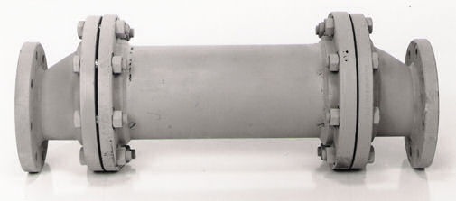
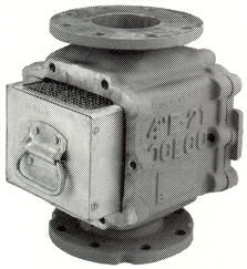
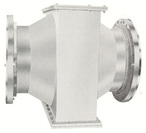
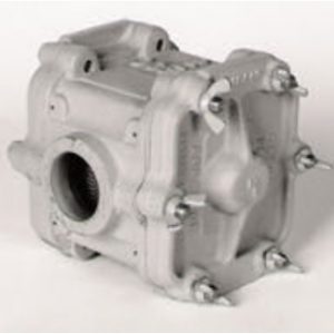
OCECO Types "P" and "PF" Flame Retarders have been used for many years in process gas lines to minimize the hazard of "flash-back". They are usually installed as near the outlet as possible and employ a retarding element designed to check an ignition of the downstream gas at the element assembly.
The element consists of corrugated and flat metal sheets rolled into a tight cylinder, which is then inserted in a steel housing. The rolled sheets are held tightly against the inside walls of the housing by tapered plugs forced into the center of the cylinder at each end.
Both flame retarder models are designed in such a manner that the center body section may be removed for inspection of the element assembly without disturbing the piping.
Flame Retarders for use in applications requiring higher pressures or non-standard materials of construction are available on special order.


